This post covers how we implemented a smart NIC on an FPGA as our final year major project, with my teammates (Chinmay & Muthukumar). The idea came from our exposure to XDP/eBPF and wanting to try out hardware offloading.
The project aimed to:
- Complete the project and get the degree.
- Design a NIC entirely with Verilog, using a pre-existing ethernet core like liteeth for serial data processing and modification.
- Connect the LAN on FPGA to the router with a standard interface such as PCIe or UART for communication between Host and FPGA (NIC).
- Build custom offloading logic onto the NIC with Verilog.
- Write NIC drivers in C for the host Linux OS to support the built hardware.
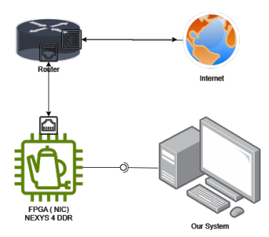
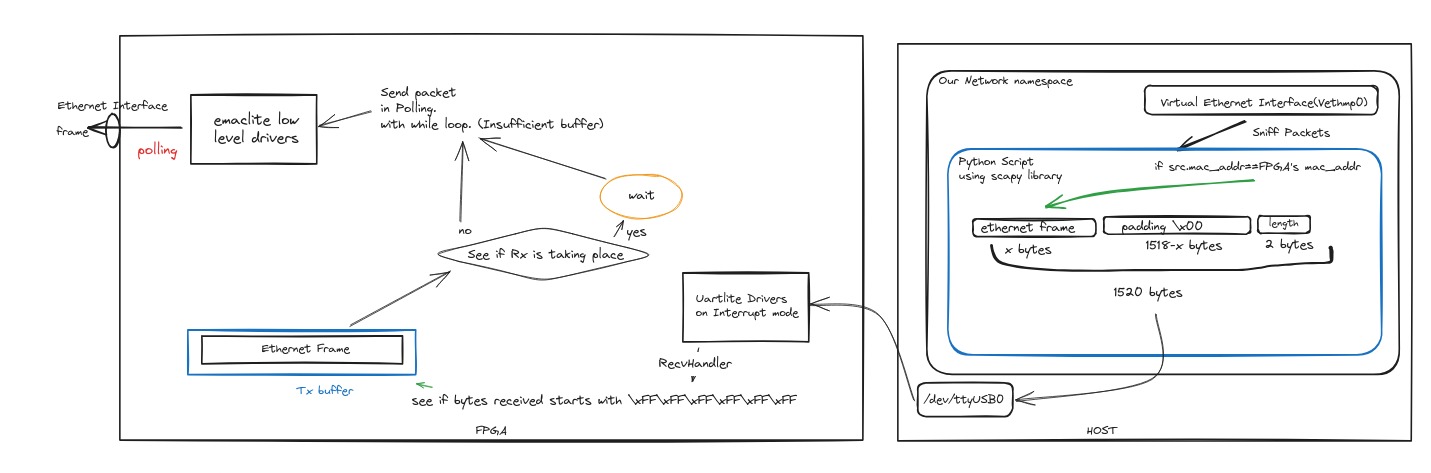
Here’s the overall architecture:
The major project edition in the title means:
- We had very little time left when we started the main work.
- Most of the project was done in the final week.
- We had to take a lot of shortcuts to get things working.
This isn’t a guide to building a production-ready NIC, but more about how to get started with an MVP if you have some experience with Verilog HDL, Linux, and C. We wanted to write this because we couldn’t find a single go-to place for this kind of project.
We had some Verilog HDL experience, but hadn’t worked with FPGAs before. It took a while to get one from the university, and we ended up with a Nexys 4 DDR (works with Vivado). This limited us to a 100mbps link on the ethernet interface and UART as the communication interface between host and FPGA.
Because of time constraints, we changed our plan:
- Instead of building transmission and reception logic entirely in Verilog, we flashed a Microblaze soft Core processor onto the FPGA and wrote the packet logic in C.
- Used custom or pre-built IPs with MicroBlaze for hardware offloading, like a T-CAM IP for a firewall.
- Most other things stayed the same.
Getting Familiar with Nexys 4 DDR and Microblaze
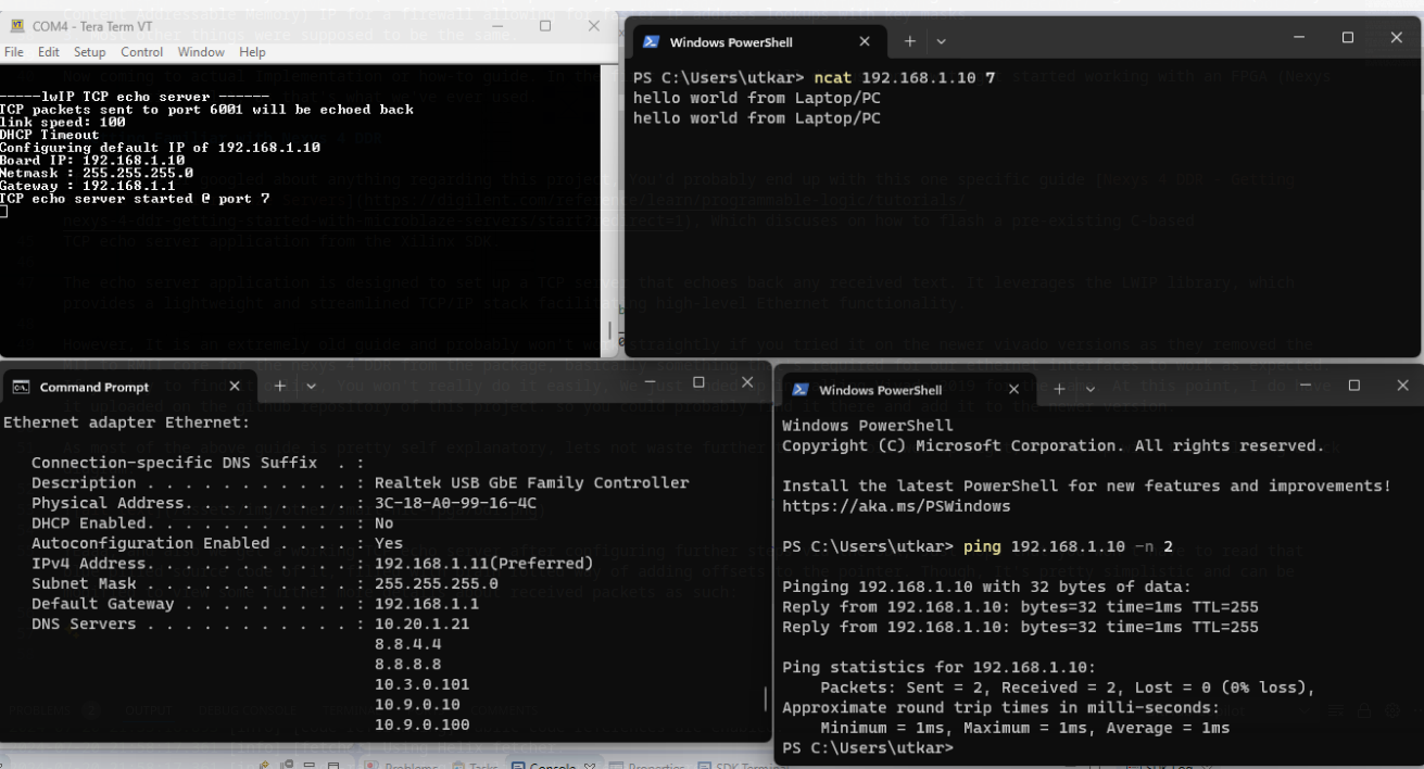
A helpful guide is Nexys 4 DDR - Getting Started with Microblaze Servers, which explains how to flash a pre-existing C-based TCP echo server application from the Xilinx SDK.
The echo server uses the LWIP library, which provides a lightweight TCP/IP stack for high-level Ethernet functionality.
However, newer Vivado versions removed the MII to RMII core for the Nexys 4 DDR, which is needed for ethernet interfaces. We installed Vivado 2019 and uploaded the necessary files to the project’s GitHub repository for use with newer versions.
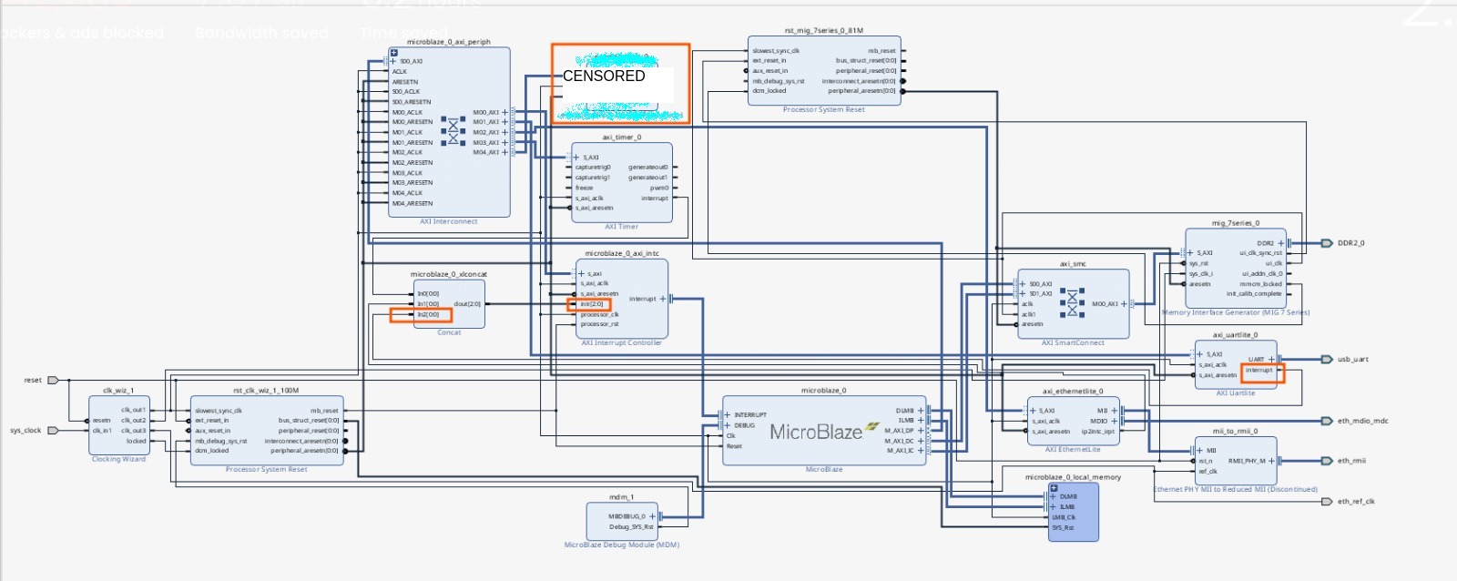
If you follow the guide, you’ll get a block diagram like this:
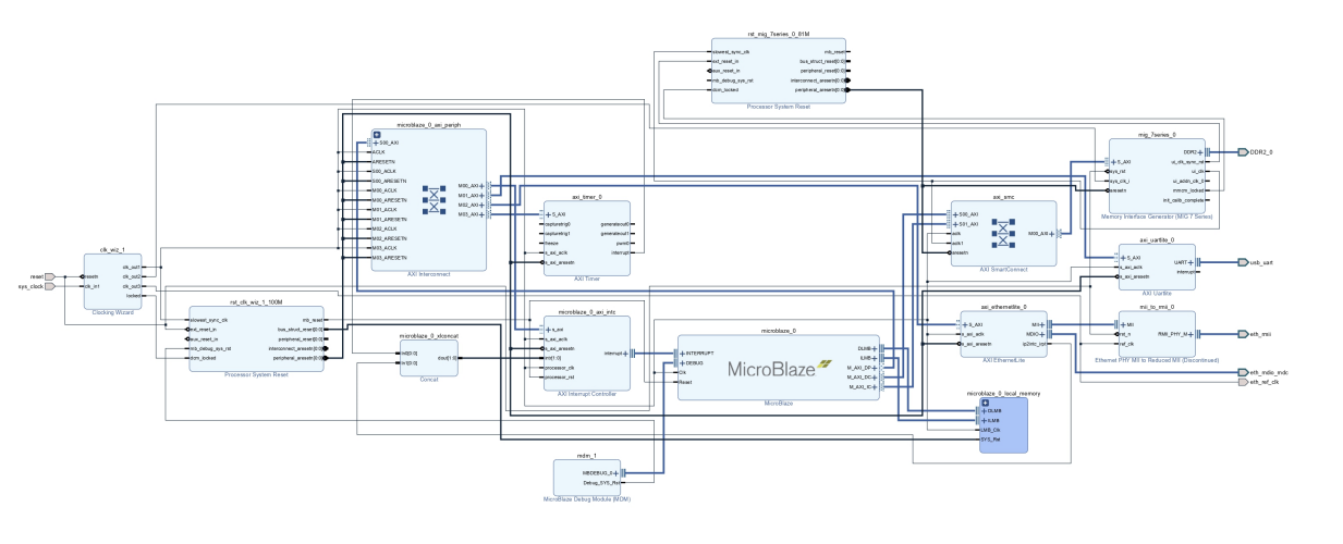
After further configuration, you get a working TCP echo server.
Capturing Raw Ethernet Frames
The echo server uses LWIP, which seemed promising at first. We thought we could configure raw sockets in promiscuous mode to monitor all incoming packets/frames, but that wasn’t possible.
Looking into LWIP’s source code, we found it uses emaclite drivers, which have documentation and examples: link.
There are two ways to use them:
- Polling Mode
- Interrupt Mode
We went with polling mode for performance reasons (inspired by DPDK).
The ping reply example was a good starting point.
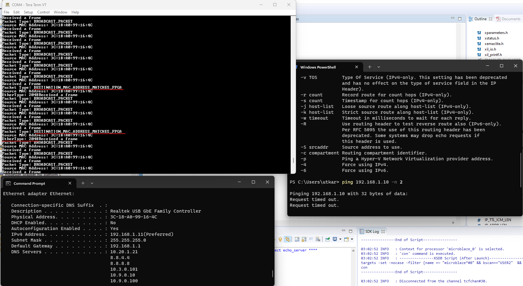
The code is straightforward and can be modified to display details about received packets:
This, along with an example of sending frames, gave us a clear path for implementing reception, transmission, and offloading/packet processing logic.
Communication between the FPGA and Hosts
Uartlite
We used Uartlite to send and receive data to/from hosts while polling with the Emaclite driver for packets from the external world. The MicroBlaze architecture doesn’t support multithreading, and polling mode is used in other drivers.
We set up interrupts with Uartlite drivers for transmission (from hosts), while packet reception happens in polling.
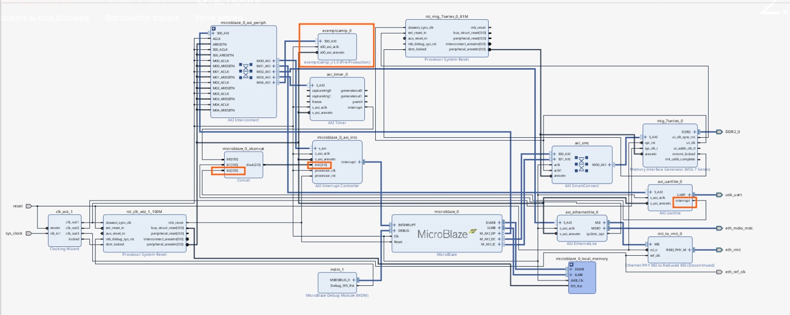
A 2:1 concat block was added to the design, following this yt video.
Here’s how the result looks, with new connections in orange:
Note: The polling functions are non-blocking, so this setup wasn’t strictly necessary.
Drivers
We needed drivers for the UART interface to act as an ethernet interface. Due to time constraints, we took a different approach.
Linux and its features
We needed an ethernet interface on the OS for applications to send and receive packets.
Linux Namespaces
Linux namespaces allow for isolated containers within the host system, each with its own network stack. This lets you test transmission and reception separately without affecting your main setup.
Virtual Ethernet Interfaces
Virtual ethernet interfaces can be created without physical hardware, acting like real ethernet interfaces. This is similar to how VPNs work.
Scapy - A Python library
Scapy can sniff packets during transmission and send packets during reception from/to an interface.
How does this all go together?

Using namespaces, a single laptop can connect to the FPGA via UART and ethernet, working in multiple network namespaces for testing. A virtual ethernet interface vethmp0 is created and configured with the same MAC address as the FPGA’s ethernet interface.
Packets on vethmp0 with the source MAC address matching the interface’s MAC address are sent via UART to the FPGA.
So, FPGA's Mac and IP address = vethmp0's Mac and IP address
At reception, packets with the destination MAC address matching the FPGA are processed and sent to the host via UART, then inserted into vethmp0 or forwarded via another vethmp1.
configuring the development environment:
A bash script simplifies the process:
ip netns add mp_nwk2
ip link add vethmp0 type veth peer name vethmp1
ip link set vethmp1 netns mp_nwk2
ip netns exec mp_nwk2 ip link set lo up
ip link set dev vethmp0 address 00:18:3E:01:EB:3A
ip link set vethmp0 up
ip address add 192.168.1.10/24 dev vethmp0
ip netns exec mp_nwk2 ip link set vethmp1 up
ip netns exec mp_nwk2 ip address add 192.168.1.12/24 dev vethmp1

ip netns add mp_nwk1
ip netns exec mp_nwk1 ip link set lo up
ip link set vethmp0 netns mp_nwk1
ip netns exec mp_nwk1 ip link set vethmp0 up
ip netns exec mp_nwk1 ip address add 192.168.1.10/24 dev vethmp0
ip netns exec mp_nwk1 python veth2uart.py
#term2
# ip netns exec mp_nwk2 bash
# ip netns exec mp_nwk2 ip link set vethmp1 up
# ip netns exec mp_nwk2 ip address add 192.168.1.12/24 dev vethmp1
Configuration:
- FPGA connected host’s IP (via USB):
192.168.1.10 - Externally connected host’s IP (via ethernet to FPGA):
192.168.1.11 - Third interface on the host for testing:
192.168.1.12
Each is present in a different namespace on the same host.
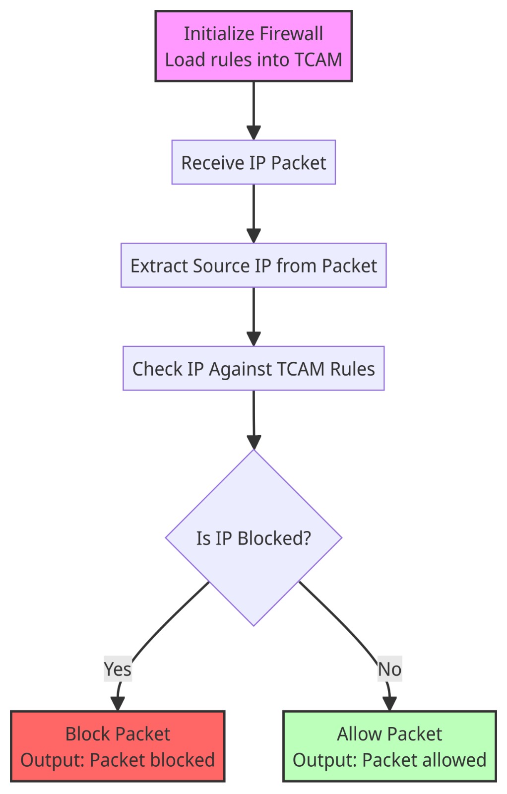
Offloading / Packet processing / Firewall
The main objective was to implement this inside the NIC to reduce host load. As a POC, a simple match action-based firewall was built, using a TCAM for fast IP address lookups.
TCAM - Ternary Content Addressable Memory
TCAM enables rapid data retrieval by searching data by content rather than address, making it suitable for networking tasks like packet forwarding.
The core consists of a memory array with data patterns (keys) and associated masks. The mask specifies bits to ignore, enabling flexible matching. Operations are performed in parallel across all entries.
A custom TCAM IP was developed, as existing ones required proprietary licenses.
Steps:
- Implement a TCAM in Verilog HDL or VHDL.
- Turn it into an IP compatible with the architecture by making it AXI compatible.
- Write MicroBlaze C drivers.
Verilog Implementation
A suitable Verilog implementation was found at mcjtag/tcam, which was easy to read and included valid/reset signals.
Building an AXI - Wrapper
The AXI protocol provides a high-bandwidth, low-latency interface for interconnecting components in an FPGA. The AXI interconnect allows the MicroBlaze processor to access and manipulate TCAM entries.
AXI Master / Slave
- The master initiates transactions.
- The slave responds to commands.
The TCAM was implemented as a slave, with MicroBlaze as the master.
AXI Lite vs. AXI Full vs. AXI Stream
- AXI Lite: Basic, easy to use, limited bandwidth.
- AXI Full: High-performance, supports complex data transfers.
- AXI Stream: For continuous data transfer, no addressing.
AXI Lite was chosen for its simplicity.
Implementation
Vivado can generate an AXI wrapper, which can be modified to add custom logic. Several resources are available, including this blog and various YouTube tutorials.
The following video was particularly helpful: Custom Slave AXI LITE Interface for Microblaze with Xilinx Vitis P1.
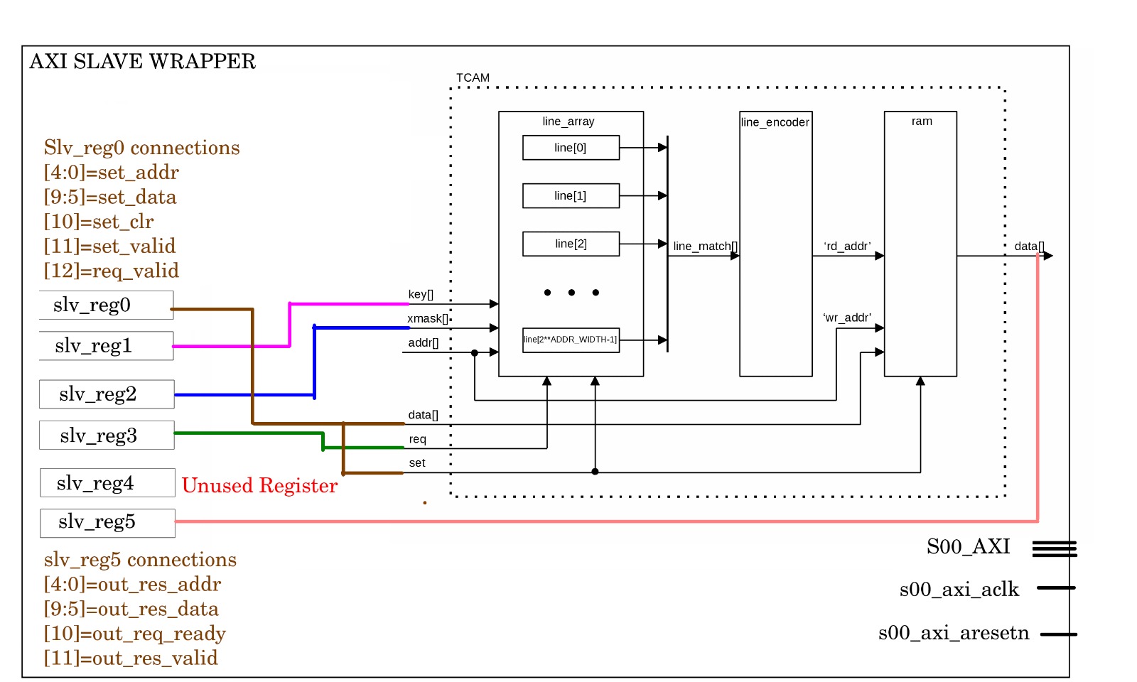
An IP package with six slave registers was created, with a 32-bit data width for the wrapper.
Instantiation of the TCAM module inside the IPNAME_v1_0_S00_AXI.v file:
    module ecemptcamip_v1_0_S00_AXI #
    (
        // blablabla
        parameter integer C_S_AXI_DATA_WIDTH	= 32,
        // Width of S_AXI address bus
        parameter integer C_S_AXI_ADDR_WIDTH	= 5
    )
    (
        // blablabla;
    );
        // blablabla;
    tcam tcam_inst(.clk(S_AXI_ACLK),
        .rst(~S_AXI_ARESETN),
        .set_addr(slv_reg0[4:0]),
        .set_data(slv_reg0[9:5]),
        .set_key(slv_reg1),
        .set_xmask(slv_reg2),
        .set_clr(slv_reg0[10]),
        .set_valid(slv_reg0[11]),
        .req_key(slv_reg3),
        .req_valid(slv_reg0[12]),
        .req_ready(out_req_ready),
        .res_addr(out_res_addr),
        .res_data(out_res_data),
        .res_valid(out_res_valid),
        .res_null(out_res_null)
        );
    endmodule
Note: The parameter values for req_key were not set correctly, resulting in a width mismatch. This is discussed further down.
Output values from the TCAM are extracted and set in the following block:
    // Implement memory mapped register select and read logic generation
    // Slave register read enable is asserted when valid address is available
    // and the slave is ready to accept the read address.
    assign slv_reg_rden = axi_arready & S_AXI_ARVALID & ~axi_rvalid;
    always @(*)
    begin
          // Address decoding for reading registers
          case ( axi_araddr[ADDR_LSB+OPT_MEM_ADDR_BITS:ADDR_LSB] )
            3'h0   : reg_data_out <= slv_reg0;
            3'h1   : reg_data_out <= slv_reg1;
            3'h2   : reg_data_out <= slv_reg2;
            3'h3   : reg_data_out <= slv_reg3;
            3'h4   : reg_data_out <= slv_reg4;
            3'h5   : begin
               reg_data_out[4:0] <= out_res_addr;
               reg_data_out[9:5] <= out_res_data;
               reg_data_out[10] <= out_req_ready;
               reg_data_out[11] <= out_res_valid;
               reg_data_out[12] <= out_res_null;
            end
            default : reg_data_out <= 0;
          endcase
    end
The video linked above provides further explanation.
The resulting TCAM IP:
After packaging and connecting it to the MicroBlaze, the final block diagram is as follows:
Writing drivers for the built TCAM-IP
Drivers were written in C to interact with the TCAM IP via the AXI interface. Vivado-generated AXI wrappers provide a template driver.
Custom functions were defined:
ECEMPTCAMIP_delayfor generating delay:
void ECEMPTCAMIP_delay(u64 d1){
    for(u64 i=0; i<d1; i++){
        for(u64 j=0;j<9999999999999999;)
            j=j+1;
        }
}
ECEMPTCAMIP_SetKeyto provide inputs:
void ECEMPTCAMIP_SetKey(u32 BaseAddress, u8 Address, u8 Data, u32 Key, u32 KeyMask){

    // Set Key
    ECEMPTCAMIP_mWriteReg(BaseAddress, 4*1, Key);

    // Set Key Mask
    ECEMPTCAMIP_mWriteReg(BaseAddress, 4*2, KeyMask);

    //	Set Address[4:0], data[9:5], set_clr[10]=0,set_valid[11]=1, req_valid[12]=0
    u32 RegData =0;
    // Mask Address and Data to use only lower 5 bits
    Address &= 0x1F; // 0x1F = 0001 1111 in binary, ensuring only lower 5 bits are used
    Data &= 0x1F;

    // Shift Address and Data to their correct positions and set in RegData
    RegData |= (Address << 0);  // Address is at bits 4:0
    RegData |= (Data << 5);     // Data is at bits 9:5

    // Set set_valid to 1 at bit 11
    RegData |= (1 << 11);       // Set bit 11
    ECEMPTCAMIP_mWriteReg(BaseAddress, 0, RegData);
    ECEMPTCAMIP_delay(999999);
    ECEMPTCAMIP_delay(999999);
    // Set set_valid back to 0
    RegData &= ~(1 << 11);
    ECEMPTCAMIP_mWriteReg(BaseAddress, 0, RegData);
    ECEMPTCAMIP_delay(999999);
    ECEMPTCAMIP_delay(999999);
    return;
}
ECEMPTCAMIP_GetKeyto read input:
u32 ECEMPTCAMIP_GetKey(u32 BaseAddress, u32 Key){
    // set Req_key
    ECEMPTCAMIP_mWriteReg(BaseAddress, 4*3, Key);

    // Set_valid to false and other stuff as well.
    u32 RegData =0;
    // Set req_valid to 1 at bit 12
    RegData |= (1 << 12);       // Set bit 11
    ECEMPTCAMIP_mWriteReg(BaseAddress, 0, RegData);
    u32 Response = 0;
    u8 ResponseReady=0;
    u32 ResponseCheckCount=0;
    while(ResponseReady==0){
        ECEMPTCAMIP_delay(999999);
        Response = ECEMPTCAMIP_mReadReg(BaseAddress, 4*5);
        // Extracting out_req_ready from Response[10]
        ResponseReady = (u8)((Response >> 10) & 0x01) || (ECEMPTCAMIP_GetRespValid(Response) &( !ECEMPTCAMIP_GetRespNull(Response)));  // Only need 1 bit

        ResponseCheckCount++;
        if(ResponseCheckCount>1000) {

        	Response = 1U << 12;
        	break;
        }
    }
    RegData &= ~(1 << 12);
    ECEMPTCAMIP_mWriteReg(BaseAddress, 0, RegData);
    ECEMPTCAMIP_delay(999999);
    return Response;
}
- Functions to extract required data from register values:
u8 ECEMPTCAMIP_GetRespAddr(u32 Response) {
    return ((u8)(Response & 0x1F));
}

u8 ECEMPTCAMIP_GetRespData(u32 Response) {
    return ((u8)((Response >> 5) & 0x1F));
}

u8 ECEMPTCAMIP_GetRespValid(u32 Response) {
    return  (u8)((Response >> 11) & 0x01);
}

u8 ECEMPTCAMIP_GetRespNull(u32 Response) {
    return (u8)((Response >> 12) & 0x01);
}
A test bench:
#include <stdio.h>
#include "platform.h"
#include "xil_printf.h"
#include "ecemptcamip.h"


int main()
{
    init_platform();
    xil_printf("Major Project TCAM-IP\n\r");
    xil_printf("--- Input 1 ---\n\r");
    u8 Address =0;
    u8 Data=2;
    u32 Key=73;
    u32 KeyMask=0;
    KeyMask |= 0xFF;
    xil_printf("Address %u\n\r", Address);
    xil_printf("Data %u\n\r", Data);
    xil_printf("Key %u\n\r", Key);
    xil_printf("KeyMask %u\n\r", KeyMask);
    ECEMPTCAMIP_SetKey(XPAR_ECEMPTCAMIP_0_S00_AXI_BASEADDR, Address, Data, Key, KeyMask);
    ECEMPTCAMIP_delay(999999);
    xil_printf("--- Input 2 ---\n\r");
    Address =1;
    Data=5;
    Key=4000;
    KeyMask=0;
    xil_printf("Address %u\n\r", Address);
    xil_printf("Data %u\n\r", Data);
    xil_printf("Key %u\n\r", Key);
    xil_printf("KeyMask %u\n\r", KeyMask);
    ECEMPTCAMIP_SetKey(XPAR_ECEMPTCAMIP_0_S00_AXI_BASEADDR, Address, Data, Key, KeyMask);
    ECEMPTCAMIP_delay(999999);
    xil_printf("--- Input 3 ---\n\r");
    Address =2;
    Data=4;
    Key=2502;
    KeyMask=0;
    xil_printf("Address %u\n\r", Address);
    xil_printf("Data %u\n\r", Data);
    xil_printf("Key %u\n\r", Key);
    xil_printf("KeyMask %u\n\r", KeyMask);
    ECEMPTCAMIP_SetKey(XPAR_ECEMPTCAMIP_0_S00_AXI_BASEADDR, Address, Data, Key, KeyMask);
    ECEMPTCAMIP_delay(999999);
    xil_printf("--- Reading Output 1 ---\n\r");
    Key=4000;
    xil_printf("Input Key : %lu\n\r", Key);
    u32 Response = ECEMPTCAMIP_GetKey(XPAR_ECEMPTCAMIP_0_S00_AXI_BASEADDR, Key);
    xil_printf("Data: %u\n\r", ECEMPTCAMIP_GetRespData(Response));
    xil_printf("Address: %u\n\r", ECEMPTCAMIP_GetRespAddr(Response));
    xil_printf("Response Valid?: %u\n\r", ECEMPTCAMIP_GetRespValid(Response));
    xil_printf("Response Null: %u\n\r", ECEMPTCAMIP_GetRespNull(Response));
    ECEMPTCAMIP_delay(999999);
    xil_printf("--- Reading Output 2 ---\n\r");
    Key=2503;
    xil_printf("Input Key : %lu\n\r", Key);
    Response = ECEMPTCAMIP_GetKey(XPAR_ECEMPTCAMIP_0_S00_AXI_BASEADDR, Key);
    xil_printf("Data: %u\n\r", ECEMPTCAMIP_GetRespData(Response));
    xil_printf("Address: %u\n\r", ECEMPTCAMIP_GetRespAddr(Response));
    xil_printf("Response Valid?: %u\n\r", ECEMPTCAMIP_GetRespValid(Response));
    xil_printf("Response Null: %u\n\r", ECEMPTCAMIP_GetRespNull(Response));
    ECEMPTCAMIP_delay(999999);
    xil_printf("--- Reading Output 3 ---\n\r");
    Key=62;
    xil_printf("Input Key : %lu\n\r", Key);
    Response = ECEMPTCAMIP_GetKey(XPAR_ECEMPTCAMIP_0_S00_AXI_BASEADDR, Key);
    xil_printf("Data: %u\n\r", ECEMPTCAMIP_GetRespData(Response));
    xil_printf("Address: %u\n\r", ECEMPTCAMIP_GetRespAddr(Response));
    xil_printf("Response Valid?: %u\n\r", ECEMPTCAMIP_GetRespValid(Response));
    xil_printf("Response Null: %u\n\r", ECEMPTCAMIP_GetRespNull(Response));
    cleanup_platform();
    return 0;
}
The video and Drivers for custom IP provide more insights.
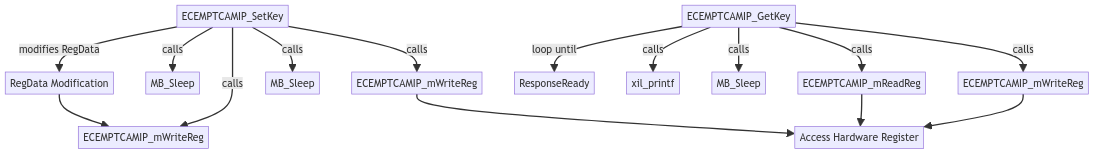
Diagram of the code flow:
Test results:
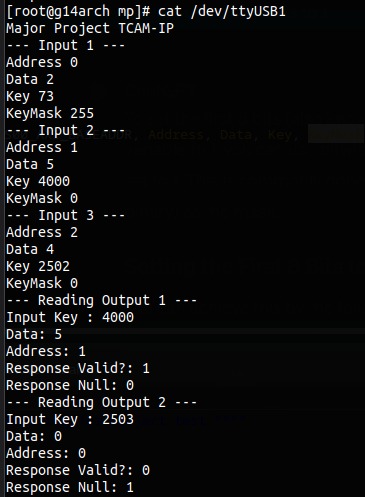
The TCAM part was completed before exams began. Later, an issue was encountered with unexpected output for different IP addresses, likely due to parameter values not being set correctly.
The match action firewall can be summarized as follows:
Ethernet Frame Reception
The following diagram illustrates the Ethernet Frame reception implementation:
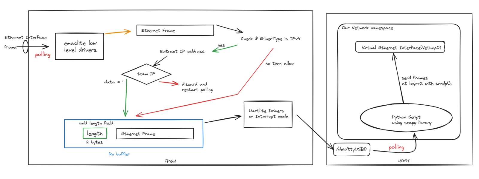
Polling for ethernet frames, the process is:
- Poll for the ethernet frame.
- Check if the Ethertype is
IPv4. - If
IPv4, extract the IP address and send it to the Firewall Logic. If dropped, return and poll again. - If not
IPv4, skip. - Prepend the frame size (2 bytes) and append newline (
\r\n) for processing. - Send the data through UART with uartlite drivers.
    while(1){
            if(FrameCaptured > 0){
                // Ignore this part for now, It's for Transmission
                XEmacLite_Send(&EmacLiteInstance,
                        (u8 *)&TxFrame,
                        FrameLength);
                MB_Sleep(10);
                FrameCaptured=0;
                FrameLength=0;
            } else {
                while(TotalSentCount<RxFrameBufferLength){
                }
                TotalSentCount=0;
                RxFrameBufferLength=0;
                while (RecvFrameLength == 0) {
                    RecvFrameLength = XEmacLite_Recv(EmacLiteInstPtr,
                                     (u8 *)RxFrame); // part that matters, starts here.
                }
                u8 Response = ProcessRecvFrame((u16 *)RxFrame); // YO your firewall goes here
                if(Response==1){
                    u8 RxFrameBuffer[1600];
                    memset(RxFrameBuffer, 0, sizeof(RxFrameBuffer));
                    memcpy(RxFrameBuffer, RxFrame, RecvFrameLength);
                    u16 length = Xil_Htons(RecvFrameLength);  // Convert to network byte order
                    memcpy(&RxFrameBuffer[1600 - 4], (u8*)&length, 2);
                    RxFrameBuffer[1600-2]='\r';
                    RxFrameBuffer[1600-1]='\n';
                    RecvFrameLength=0;
                    RxFrameBufferLength=1600;
                    memset(RxFrame, 0, sizeof(RxFrame));
                    XUartLite_Send(&UartLite, (u8*)RxFrameBuffer, RxFrameBufferLength);
                }
            }
        }
A Scapy-based Python program expects data from the UART COM Port:
import serial
from scapy.all import Ether, sendp, UDP, IP , srp
from time import sleep

ser = serial.Serial('/dev/ttyUSB1')  # replace with your serial port
frame = b""
capturing = False
while True:
    try:
        data = ser.readline()[:-2]
        framelen = int.from_bytes(data[-2:], 'big')
        # if(framelen < 1520): idr whats this doing here
        frame = Ether(bytes(Ether(data[:framelen])))
        print(framelen)
        frame.show()
        sendp(frame, iface="vethmp0")
        # srp(frame, iface='vethmp0')
    except Exception as e:
        continue
Testing by pinging from an external host (192.168.1.10) to the host/FPGA (192.168.1.11) shows ARP request packets.
Ethernet Frame/Packet Transmission
Transmission is straightforward.
Process:
- Sniff for packets with Scapy:
from scapy.all import sniff, Ether
import serial

ser = serial.Serial('/dev/ttyUSB1')
def handle_frame(frame):
    # This function will be called for each captured frame
    # Here you can analyze or forward the frame as needed
    #print source and destination mac address
    if((frame.src).lower() == "00:18:3e:01:eb:3a"):
        print(frame.summary())
        print("Source MAC: " + frame.src)
        try:
            tosend = bytes(frame)
            original_length = len(tosend)
            tosend = tosend.ljust(1518, b'\0')  # pad with null bytes to 1500 bytes
            tosend += original_length.to_bytes(2, 'big')  # append length at 1501st byte
            ser.write(tosend)
        except Exception as e:
            print("Error writing to serial port")
            print(e)

sniff(iface="vethmp0", prn=handle_frame, store=False, lfilter=lambda x: x.haslayer(Ether))
- Check if the source Mac Address matches the FPGA/
vethmp0. - Pad the frame to 1500 bytes with null bytes.
- Append length.
- Send the packet through the UART serial COM port.
The interrupt is invoked, and the starting bytes are checked for the Ethernet frame signature.
Reception of a packet in progress is checked to avoid interference.
The data is processed, the frame is extracted, and sent through the ethernet interface via emaclite drivers.
void RecvHandler(void *CallBackRef, unsigned int EventData)
{
    if(EventData==TX_BUFFER_SIZE&&
            TxBuffer[0]==0xFF&&
            TxBuffer[1]==0xFF&&
            TxBuffer[2]==0xFF&&
            TxBuffer[3]==0xFF&&
            TxBuffer[4]==0xFF&&
            TxBuffer[5]==0xFF
        ){
        FrameLength = ((u16)TxBuffer[TX_BUFFER_SIZE -2 ] << 8) | TxBuffer[TX_BUFFER_SIZE - 1];
        if(FrameLength<XEL_MAX_FRAME_SIZE){
            memcpy(TxFrame, TxBuffer, FrameLength);
            FrameCaptured=1;
            XUartLite_Recv(&UartLite, TxBuffer, TX_BUFFER_SIZE);
            // Rest is handled in the code shown above in Reception section.xD
        }
    } else {
        // invalid data, reset fifo and begin again?
        XUartLite_ResetFifos(&UartLite);
        XUartLite_Recv(&UartLite, TxBuffer, TX_BUFFER_SIZE);
    }
}
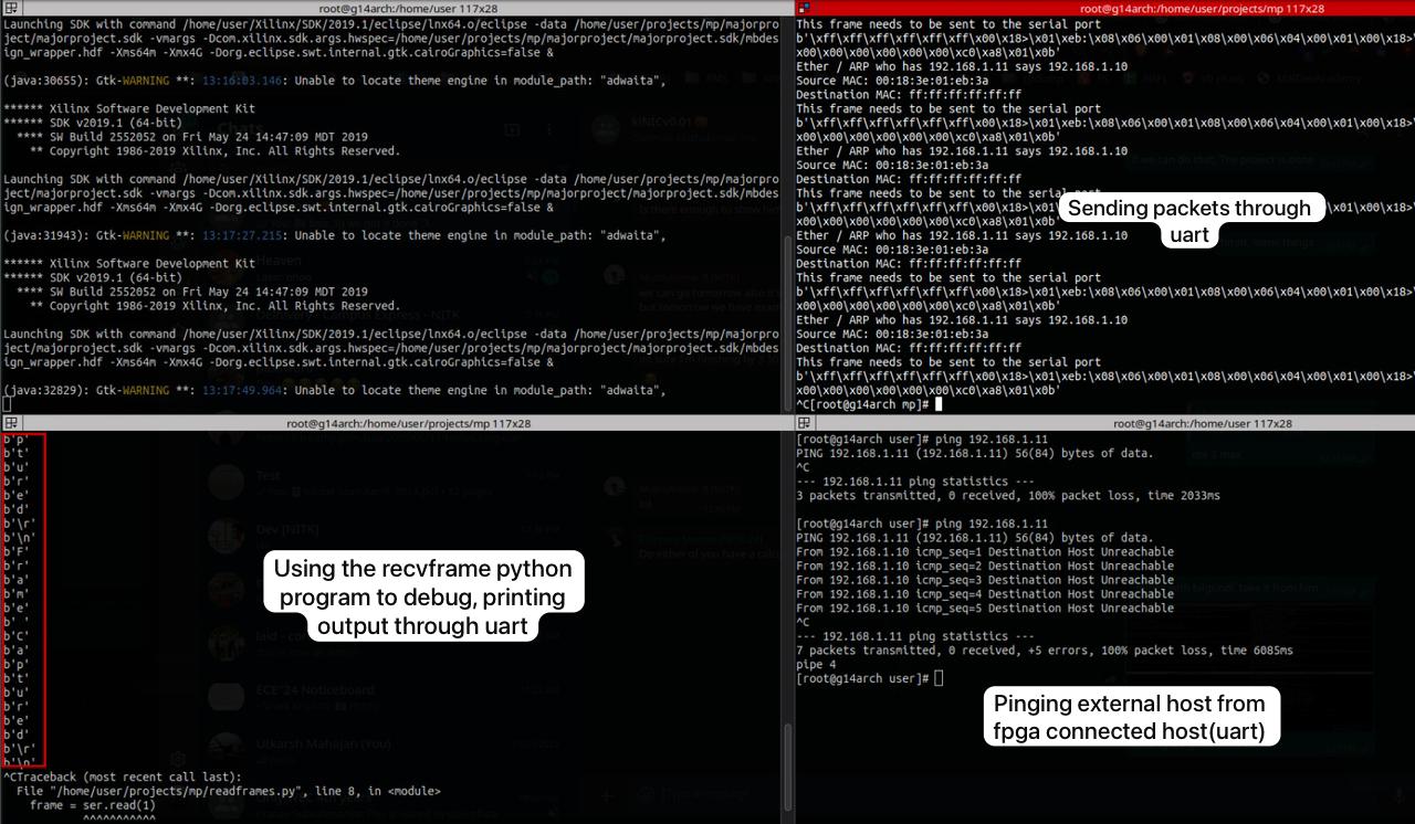
Testing by pinging the external host (192.168.1.11) from FPGA/Host (192.168.1.10) shows ARP packets.
Combining everything
The components were separately present and working well. They were combined as planned.
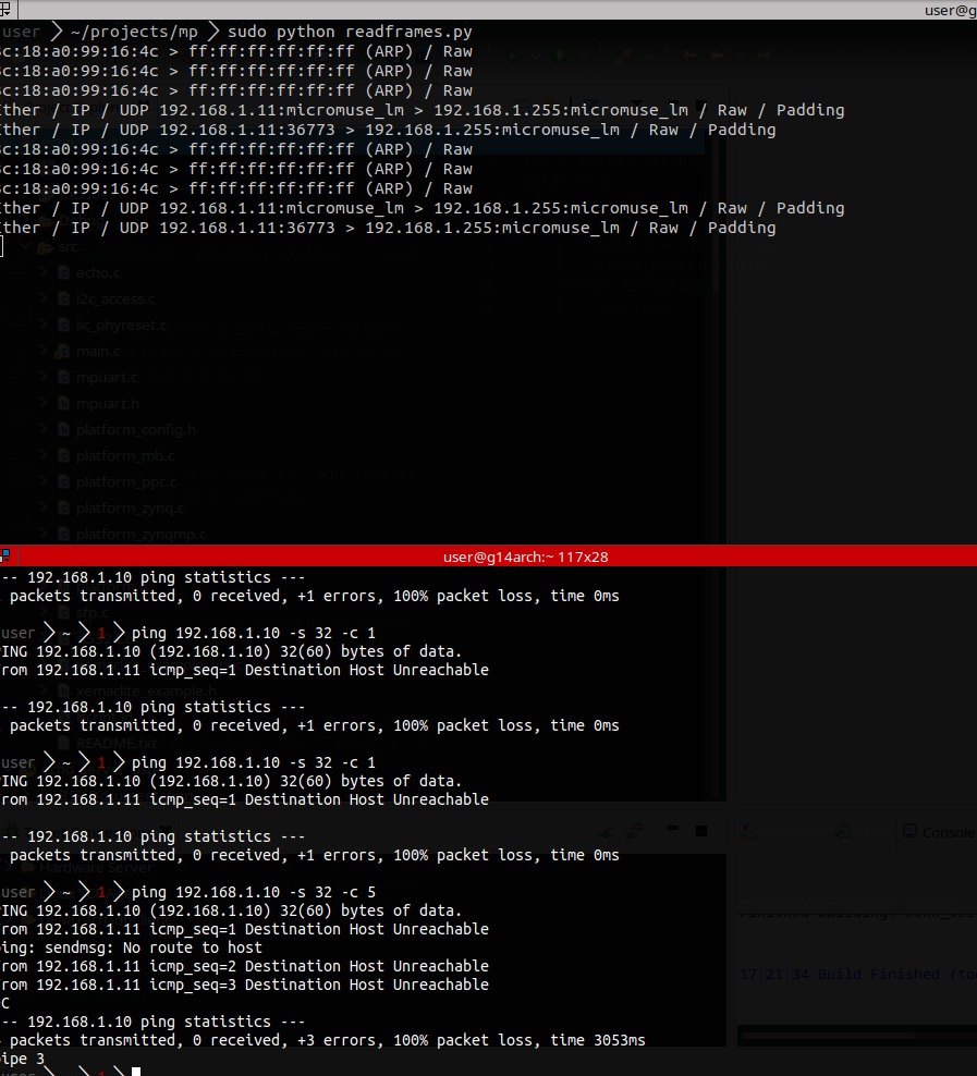
Testing by pinging host (192.168.1.11) from veth (192.168.1.10) produced the following output:
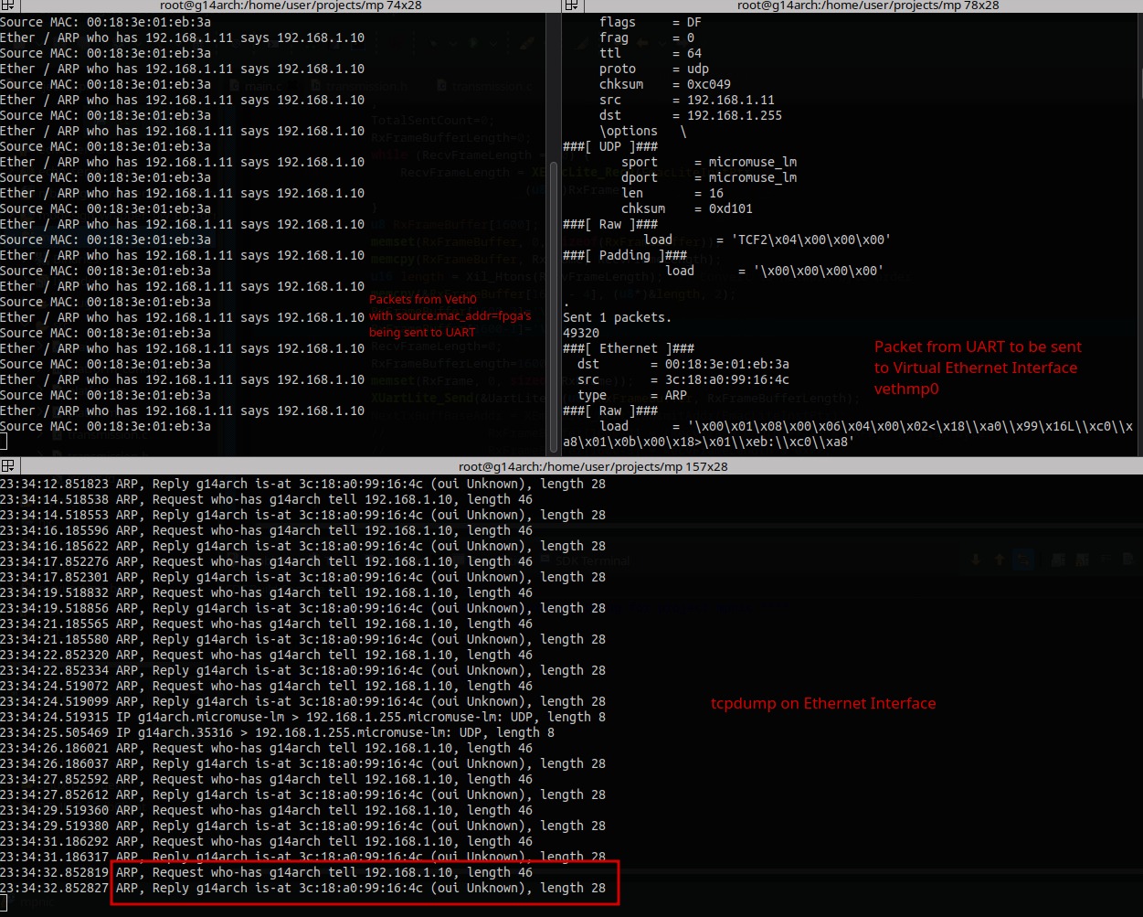
However, instead of ICMP echos, only repeating ARP packets were observed.
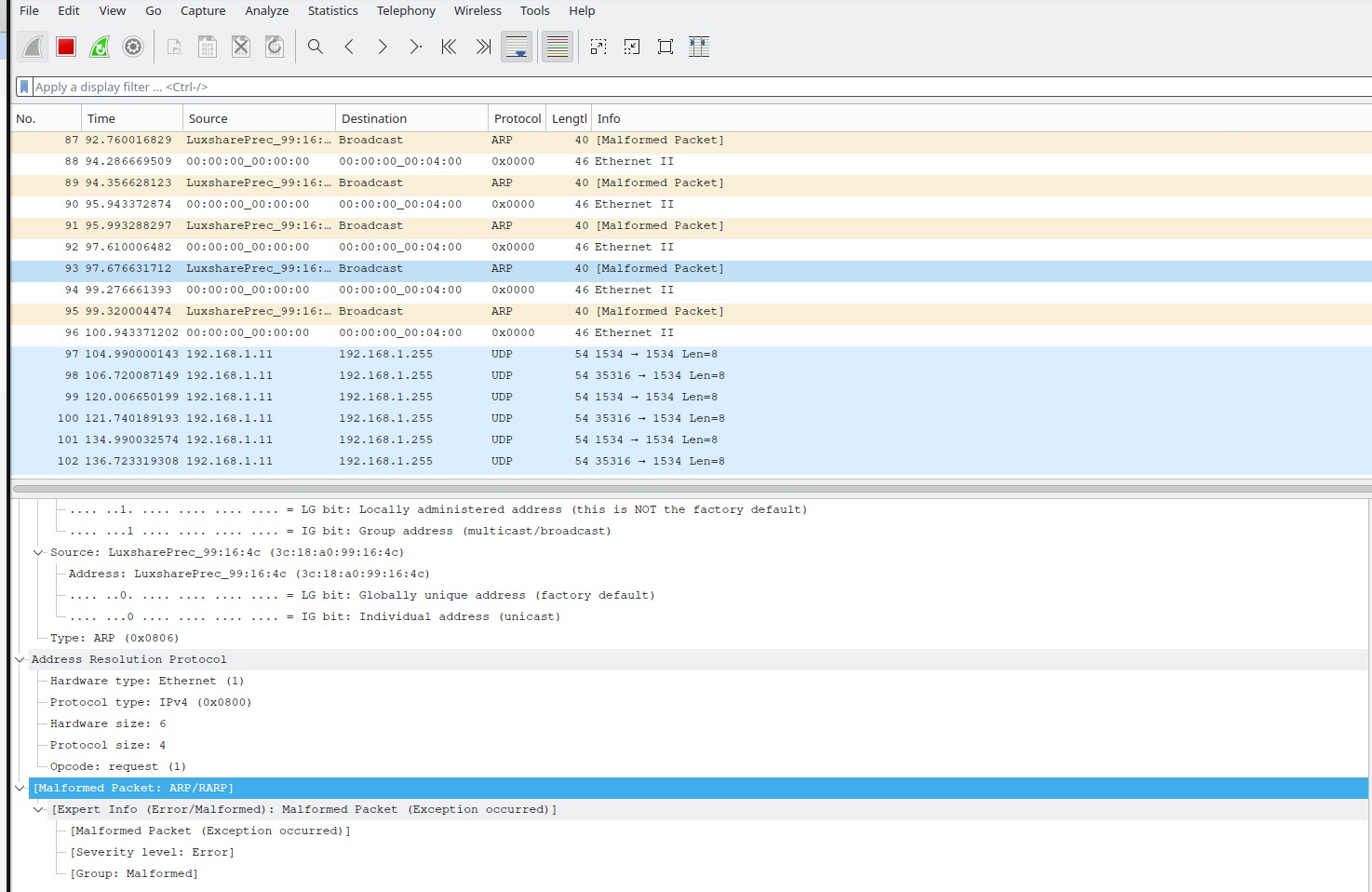
Wireshark revealed that packets sent from FPGA to the host via UART were malformed.
After considering the time left for the report and presentation, and needing to return the FPGA, we wrapped up the project.
Resources used or referenced:
- Inbasekaran Perumal
- NITK’s CSE Dept Open Source Networking Technology Course Notes
- Nexys 4 DDR - Getting Started with Microblaze Servers
- Multiple UARTLite Instantiation w/ Microblaze
- NetFPGA-SUME-TCAM-IPs
- Xilinx Emaclite Example
- Xilinx Emaclite API Index
- hBPF
- Cornell ECE5760 Final Project
- Austin Marton Gist
- Ethernet Raw Data Sniffing (Xilinx)
- Using lwIP to Send Raw Ethernet Frames (Xilinx)
- YouTube: UARTLite 2:1 Concat Block
- AMD PG318 TCAM Introduction
- eth_debug